Data center cooling and refrigeration units
- Maximum free cooling thanks to high cold-water temperatures
- High COP values thanks to low recooling temperatures
- Minimum refrigerating machine running time thanks to use-dependent load removal
- Safety through n+1 redundancy
In a data center, on the one side the heat must be removed from the data center area, and on the other the cold energy must be provided. A primary side (data center heat) and a secondary side (cold generation) can thus be defined. For both system parts, in some circumstances the tier 3 rule is also applied, i.e. n+1 redundancy.
The computers installed in a data center mainly generate heat alongside the computing power. This heat must be removed. The installed computers thereby have an important role to play. Internal temperature monitoring systems let the computer-internal cooling system run according as needed. In the case of air cooling, the computer circuit board is equipped with a temperature sensor that constantly monitors the surface temperature of the circuit board. If the temperature increases, the fans are started. As a consequence of this, only the amount quantity of cold air that is needed by the computers should be introduced into the data center area. This is ensured if the same pressure is present on both sides of the computer, therefore if there is no differential pressure. This is a task for the regulation of the cold air volumes.
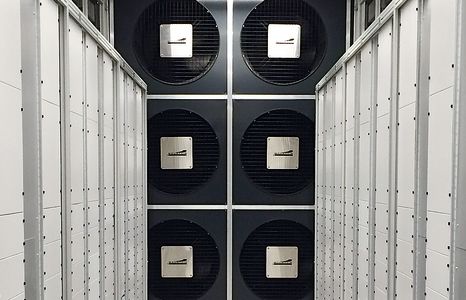
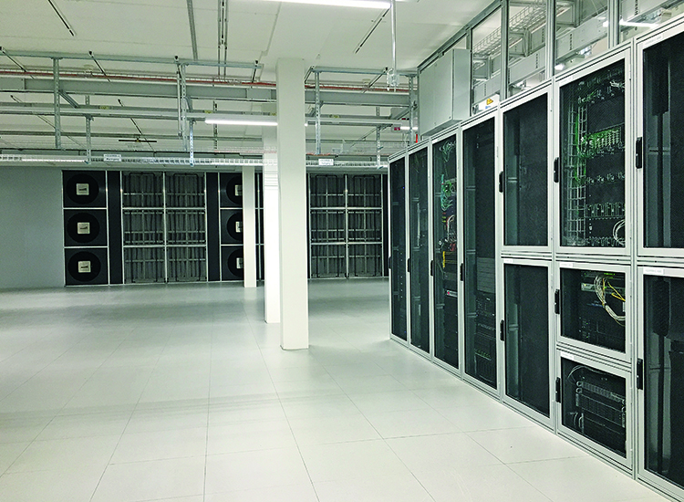
The data center surface are also divided into different zones. Is only one tenant present or are there various independent tenants who share the data center? The rack rows are very standardised nowadays. A computer has a defined width and a variable height, depending on its power. This forms a rack row. One possibility is the creation of a warm and a cold aisle for the spatial separation of the rack rows. In the cold aisle, the necessary cold air is blown in and provided for the computer cooling. In the warm aisle, the use-dependent warmed air is sucked out via the cooling module and cooled back down to the input temperature. The time of day and the business activities influence the power requirements. Sophisticated controlling makes it possible for the circulating air cooling units to only require that which is actually necessary at any given point in time. For this purpose, Mountair has developed so-called “Cooling wall modules” that are adjusted to the spatial and power-dependent conditions – design and construction are different in every project. Below you will see an example of a cooling wall and system description with a 2+1 redundancy design and a cooling power of 100 kW per rack row.
A cooling wall module has a nominal performance of e.g. 100 kW and is separated into (three) zones. If a zone fails due to a defect, the two remaining zones are able to provide the required 100kW of cooling power.
A cooling wall module is assigned to a server row. The servers are all installed on the same side. Cold air is sucked in from behind (cold aisle) and the air heated by the servers is blown out (warm aisle) in front (user side). The servers convey the air required for the cooling from the cold aisle to the warm aisle with their own computer fans.
The cooling wall module is tasked with sucking out the heated air from the warm aisle, cooling it down and blowing it back into the cold aisle. The cooling wall works as a Circulating Air Unit (CAU).
The cold water required for the cooling (20°C) is provided redundantly. There are two water networks (A+B). In normal operation mode, each zone provides 33.3kW of cooling power, in emergency operation mode a zone can provide up to 50 kW of cooling power. Each zone is equipped with its own fan. In normal operation mode, a fan conveys 10 000 m3/h. In emergency operation mode, a fan conveys 15 000 m3/h per zone.
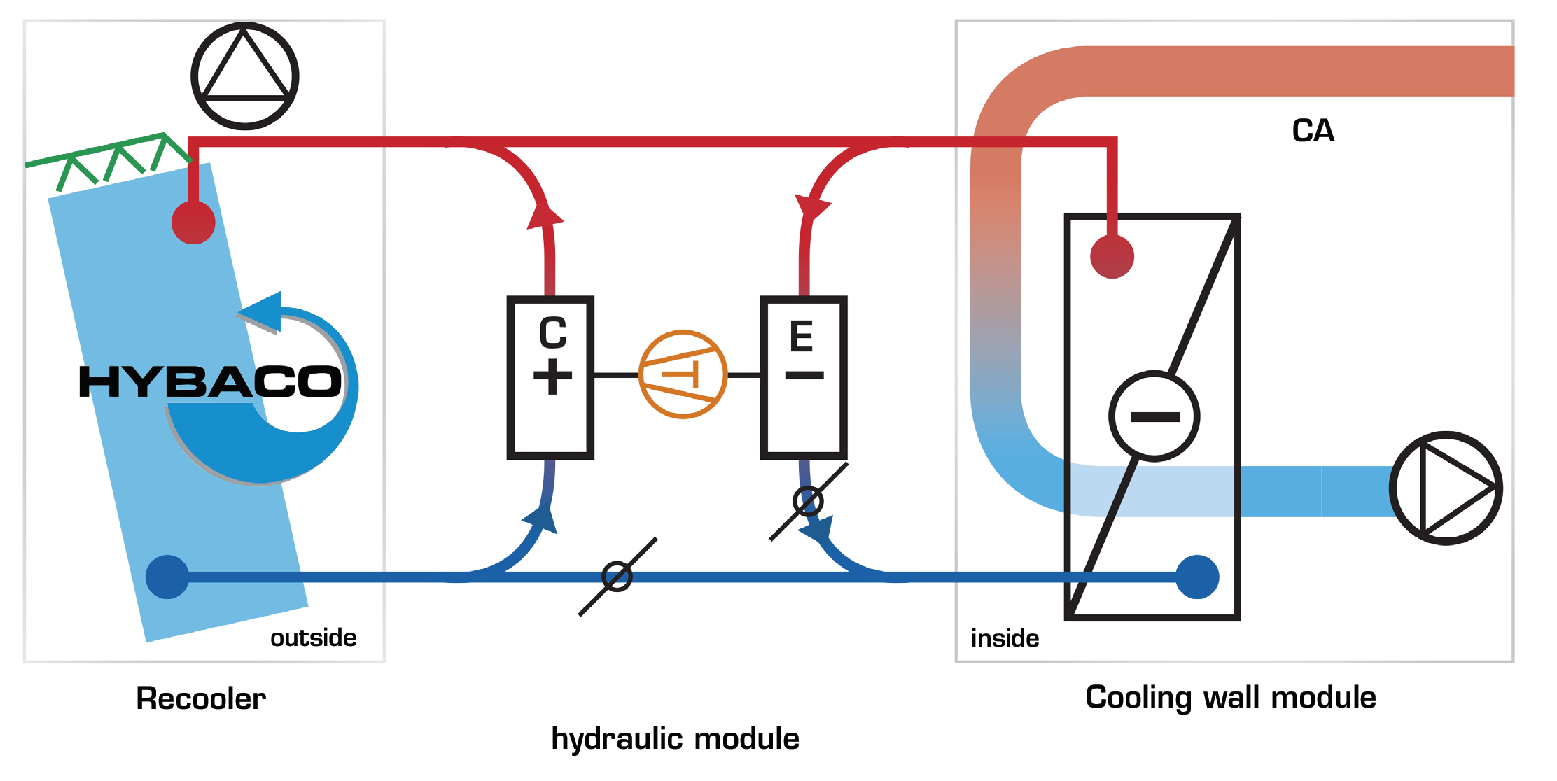
The CAU cooling wall module is designed as a deflector module. The heated air (34°C) is sucked into the module via a filter wall and cooled down by a water-air heat exchanger (24°C), in order to then be conveyed back into the cold aisle. The warmed water (30 °C) is cooled back down to the required 20°C through cold and refrigerant units.
The CAU cooling wall modules are operated so that they work as well as possible. This means that only as much air is conveyed as necessary. The air should heat up as much as is permissible in the server computers. The air volumes required for this are optimised. If the delta-T decreases, the fans are cut back. The delta-T should ideally be as close as possible to the 10 K value.
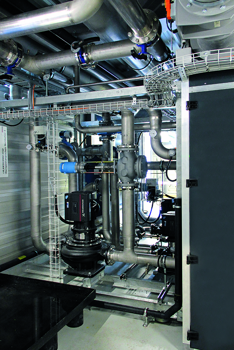
Regardless of how the computers in the data center area are cooled, cold energy must be provided for it. We speak of cold water that is often used in the CAU cooling wall module heat exchangers. Even in case of direct computer cooling with cold water pipes within the computer, cold energy in the form of cold water is necessary. Data center computers require very cold conditions in order to be able to run efficiently. As already described, the computers have an internal temperature regulation. A data center computer works at best in the 20–40°C range. This fact means that relatively high cold-water temperatures are sufficient. It is therefore not necessary to provide 6°C CPW. Additionally, this brings further disadvantages such as condensation.
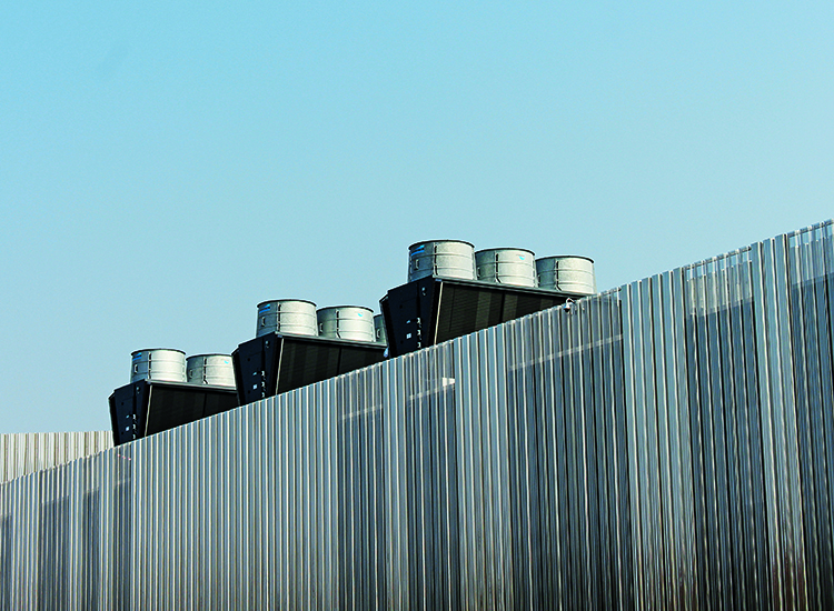
Fundamentally, the following applies: the smaller the lift, the more efficiently a cooling system can be run. The smaller the lift, the higher the cold-water temperature (regardless of the load removal on the secondary side of the refrigerant machine). The cold-water temperatures must therefore be chosen so that the heat exchangers are not too high (higher pressure loss = constant energy consumption), but however also so that the cooling energy can be efficiently prepared. It is therefore possible to work with 18–20°C cold water flow temperatures, in order to simultaneously cool the data center air from 34°C down to 24°C. The choice of a high cold-water temperature has the advantage of being able to work with the maximum possible free cooling and of reducing the refrigerating machine operating times.
